

A Retro Retrofit: Improving Efficiency in an Older Home
/With all of our focus on innovative, energy-saving equipment at Small Planet Supply, it was a total surprise that the house Albert Rooks (Small Planet Supply) and I recently purchased in Olympia was a 1938 home. While we would love to say it was the structure we fell in love with, it was probably the gardens that made us feel like we had found a new place to land in Washington state.
Our Second Retrofit
In 2013 we had bought a 1970s two-story condo (1/2 of a duplex, which was fully detached). We had pulled it down to the studs and retrofitted it to almost Passive House efficiency, utilizing the first Sanden (now SANCO2) used as a combi in North America, our first Zehnder system and covered it in ThermaCork. The goal of this retrofit was to bring the house up to the 2010s in terms of look, energy efficiency and style.
We loved living in the house but moved to Canada full-time in 2018 to focus on bringing our products to Canada. While we were gone, we rented our house to our daughter, who loved living in the house too.

The project: Classic 1938 home with no wall insulation in original building, but improved attic and floor system insulation with spray foamed joist rims to crawl spaces. Can we reduce the loads of these “classics” and not turn them into a “tear down”?
When we thought about returning to the USA, we had to acknowledge that we would probably need more space than our retrofit could provide, especially if we continued to need to work from home or if one of our aging parents needed to live with us. So, buying a slightly larger house made sense. However, actually buying another house wasn’t easy. After making offers on multiple houses, we finally (to our surprise) had an accepted offer on this 1938 home, which was on the city’s historic register.
Goals for the 2020 Retrofit: Reduce Energy Use, Get Off Gas, Achieve Cleaner Indoor Air & Retain Historic Charm
Once the home was ours, Albert started doing some investigation about what kind of changes the home would need to be more energy efficient. Fortunately, the home was in very good condition for its age, so the first focus would be to see how far we could improve the energy consumption solely by using the latest tools/technology that we have available. Our hope is that if can select the most efficient state-of-the-art mechanicals with strategic airtightness strategy, we can learn how to electrify an older building like this one at an affordable costs rather than deconstructing the building and reconstructing it with a new building envelope.
Where We Started: Equipment and Mechanicals
When we moved in the mechanical systems powering the home were: gas water heater, electric heat pump forced air heating and cooling system (using home’s original ducting). The house also had a gas stove, a gas fireplace and a wood-burning fireplace.
Selecting New Equipment
One of the first things Albert considered was changing to a newer generation more efficient heat pump with a lower GWP refrigerant. This would use the central distribution system already in the house. However, when Albert inspected the house ducting throughout the house, he discovered it was really old, really dirty and he determined it would be difficult to seal the ducts to bring up the performance level. He came away from the inspection feeling that using the current ducting system might not work well. This decision was reinforced when the first two days in the house when we ran the central air-conditioning in the house smelled so bad we decided to turn it off, preferring to instead sweat through a number of high 90-degree days. This experience made the decision to move to a ductless system much easier. Small Planet had just taken on the Midea ductless line, so this was a chance to try it out. Ductless systems reduce energy consumption since air isn’t being pushed through long air ducts and the air stays cleaner since it isn’t traveling through old ducts, as it would using the central ducting system.
Heating and Cooling System Configuration
We worked with Alpine Ductless and Les Robertson to create a system of heating and cooling across our home using the Midea system. The Midea is inverter driven, which means the compressor motors can be controlled in very small increments from low to high, rather than a compressor that comes on at one speed, resulting in a more efficient (and quieter) system. Looked at layout of the house and matched it up with a ductless system that used four heads (distribution points) that run off of one outdoor condenser unit. Sized the condenser to the heat load and installed the system.
In an effort to keep the look of the vintage home, we used low wall cassettes as they look more traditional, like a radiator. The only exception was the family room where a high wall cassette could be hidden in a blind corner. We worked with the installer to minimize piping and conceal as much of the line set as we could. After the system was installed, the entire heating and cooling distribution system could be removed from the basement, which gave us a pathway to run our Zehnder ventilation system. The whole house ductless system took about three days to install.

Midea 48kbtu - 5 zone condensor

Low wall CASSETTES have that classic “radiator” look where high wall heads look out of place.

18K High Wall head hides in a blind corner, but it still serves the room UNOBTRUSIVELY.
Wildfire Interruption & Zehnder Temporary Install
Before our ductless system was completely installed, we, like the rest of the West Coast were struggling to live with very unhealthy levels of smoke. Luckily our Zehnder Q had already arrived, so Albert set it up in the middle of our family room where it cleaned our indoor air, since we didn’t have our system hooked up yet. As weird as it looked, tt really did improve the air in the house and it definitely let our new neighbors know that their new neighbors were out-of-the-box thinkers.
Zehnder HRV System Installation
Once the ductless system was installed, it was time to permanently install the Zehnder. To install the Zehnder HRV, Albert placed the unit in the basement, ran some ducting through a a crawl space to the outdoors to get our fresh intake air. We used the old furnace system to push the Comfotubes through, providing fresh air in the living areas and pulling out stale air from the kitchen and bathrooms.

Albert sets up the Q 450 with filter case to collect room air and pass it thru the f9 filter. We felt a DIFFERENCE in about 20 minutes.
Albert found an unusual way to get rid of the system exhaust – the building’s living room chimney. The chimney had two channels with 7” holes. Albert used on of the the 7” holes in the chimney was the perfect diameter to place the exhaust duct. The end result is the exhaust air from the Zehnder goes straight out the tube in the chimney. As far as we know, this is the first time that someone has tried this configuration with a Zehnder system.

A single run of comfoflex with a home made plate to replace the foreced air ducts. The bedroom’s ORIGINAL floor REGISTER is above.

A new MULTI-TUBE PLENUM: The two tubes on the right are the first floor bath now acting as a return pathway. The single left tube is a supply to a bedroom.

The Comfowell Filter Case with its door open to change filters. The filter shown is an f9 (Merv 15). Other options are activated carbon or f7 (merv 13/14).

The Q 450 on its stand with comfopipe exterior runs, two silencers with one filter case. It was surprisingly easy to instal.
For interior runs, Albert set up silencer and box inside the basement and started running the 3 ¼ “diameter Comfoflex tubes through all the supply points (dining room, living room, family, bedrooms) and ran it through the room registers. Albert utilized the old system ducting, fishing the new Comfoflex tubes through the ducting, into each room. In each room he created a new transition, sealing the registers after the new transition had been created. He followed the same process for the returns. Each bathroom had a ducting system to supply heat in the older system so just connected it as a return and hooked it up to the Comfoflex and it worked just great.
After hooking up the entire system, Albert checked the flow values with the flow meter and everything was right at design. The Q was so easy to use, he was able to do his own commissioning. The commissioning went really well, and Albert didn’t have to make any significant changes. There was plenty of flow in all locations and registered very near the design flows. Because we used the Q series, the system self-balances and could input the design flows into the Q, so Albert was able to his flow values automatically from the Q. It was very easy to achieve the design even with this unusual distribution design but Albert that it would have been almost impossible to commission the system without a Q because the exhaust is going up the chimney and that would be a very hard area to read the flow. Albert was able to hook up the whole system (by himself) and commission it in four days.
Replacing the Gas with an Electric Heat Pump Water Heater
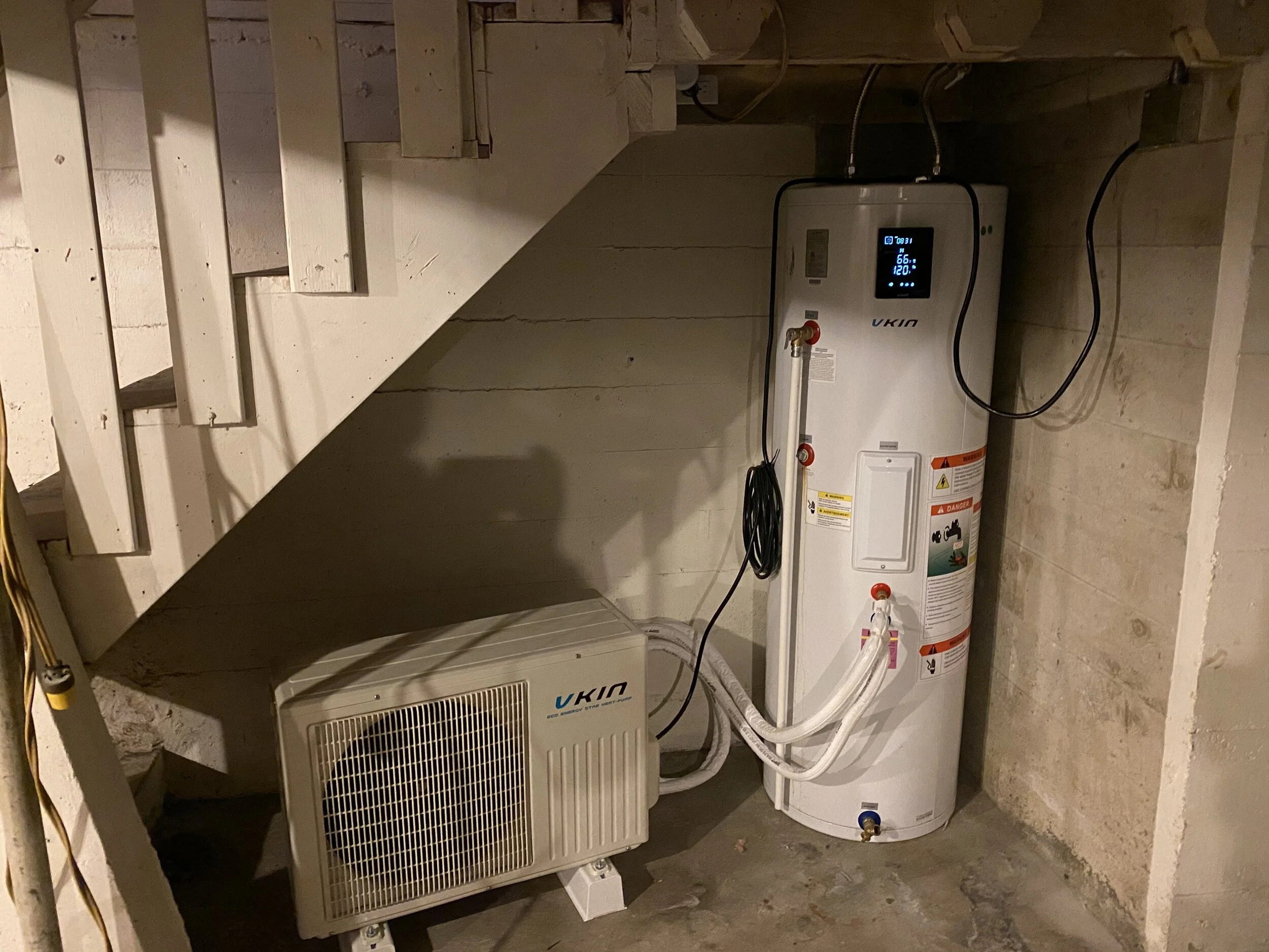
A new heat pump water heater being tested in the basement. the unit has UL and CSA CERTIFICATION. AHRI testing shows good COPS. So far no cold showers.
The water heater installed in the house was a gas water heater. Our goal is to remove gas from the building. We have a new system from ECO2 systems that we wanted to try. We had a sample so we decided to try it in our house to see how it works. The new system is a split system like the SANCO2 and uses standard refrigerants. It is smaller and costs a little bit less than the SANCO2. Based on testing documents we reviewed, it’s really quite efficient, achieving a COP of up to four. Also, different than the SANCO2, this unit is a hybrid system, so it uses both heat pump function and electric resistance coil. The refrigerant uses the electric resistance to help it make heat in lower temperatures. Like the SANCO2, the system tank goes inside and the heat pump goes outside.
For our trial purposes we have our heat pump inside in the basement right next to the tank. We diverted the water from the gas water heater and wired up the power supply to the new water heater. So far it is meeting our domestic hot water needs. It is a small system with a capacity of 12,000 BTU, which is probably enough for a family of four. We are using a 50-gallon tank and so far it’s working just fine. Currently we have the heat pump running in hybrid mode, but we will experiment with heat pump only mode (which is more efficient) in the future and see if it can still keep up with our hot water demand.
Implications of Pump Placement and Next Steps
Having the pump in the basement means we will be stealing some of the heat from the house but the rest of the house is pretty disconnected from the basement (where the unit is located) and it is a small capacity compressor – so it’s certainly reasonable. Where the system is located now it will never see any cold temperatures, so it’s a pretty soft test. The next step will be to put the compressor unit outside, where we live in the Puget Sound area. We do get some cold overnight lows, so we’ll get to see more about how it performs in colder weather. The system is rated to where we get some cold overnight lows and see how it performs. It is rated to -25 celsius. It does have UL and CSA certification already, so we believe it’s suitable for the climate, we just want a chance to test it out in a few applications before we put it out into customer houses.
Next Steps
With a good start on the mechanicals, our next step will be to focus on increasing airtightness in the home. Currently Albert’s visual assessment shows there is plenty of blown-in cellulose in the attic spaces. However, we suspect there is no insulation in the walls, which will make for a very interesting winter. We are going to set up a time to have a blower door test done to better understand what the current level of airtightness is and where we need to target our work to increase airtightness.
If we match up with state-of-the- art mechanicals, we can see how to electrify an older building like this at some affordable costs rather than deconstructing the building and reconstructing it with a new building envelope.